Wireless Infrared Communication Link System Circuit Diagram IR Communication Basics. IR radiation is simply light that we cannot see, which makes it great for communication. IR sources are all around us. The sun, light bulbs, or any anything with heat is very bright in the IR spectrum. When you use your TV remote, an IR LED is used to transmit information to your TV.

DIY - IR Module: A sensor is a device that detects and responds to inputs from the physical environment. The input can be light, heat, motion, moisture, pressure, or any other environmental phenomena. IR LED's are commonly used in conjunction with the IR receiver to support a wireless communication between 2 or more devices. Step 3: 2. IR Overview of IR LEDs, IR Photodiodes, and TSOP1738 . IR LEDs, IR Photodiodes, and TSOP1738 . IR communication makes use of IR (Infrared) waves from the electromagnetic spectrum. An IR LED is used to transmit data wirelessly in digital form (0 - LED OFF or 1 - LED ON). An IR photodiode or IR phototransistor receives this data.

IR Module : 12 Steps (with Pictures) Circuit Diagram
Intro to IR Circuits: IR is a complex piece of technology yet very simple to work with. Unlike LEDs or LASERs, Infrared cannot be seen with the human eye. So in this Instructable, I will demonstrate the basic use of Infrared through 4 different circuits. The circuits wil…

IR Communication. IR or infra-red is a common and easy to use wireless communication. The light of IR is visible like similar light, have a low frequency but slightly longer wavelength. The IR LED detects and works at 980 nm (nanometer), that's considered near to infra-red. IR radiation is basically a light that
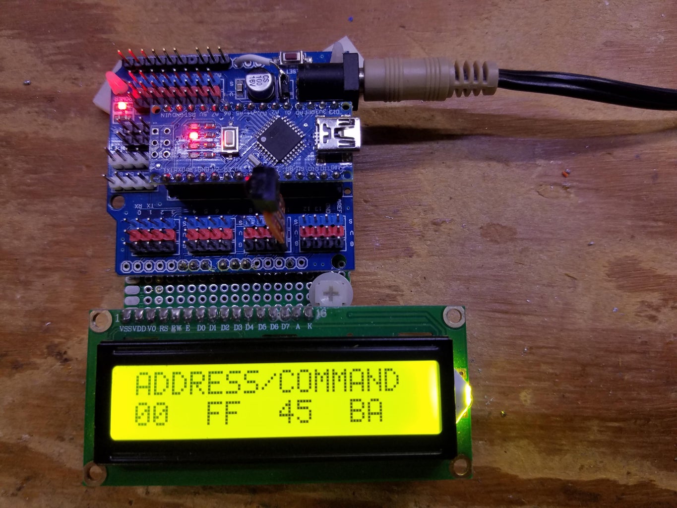
PDF Ir Communication Using Arduino Uno Circuit Diagram
Step 1: Gathering Components. Gathering the components for your DIY IR blaster is a crucial first step in this exciting journey. Each component plays a pivotal role in the construction and functionality of the device, and ensuring that you have all the necessary materials will set the stage for a smooth and successful project. The methodology for developing a IR Communication using Arduino involves several key steps: 1. Project Description: The goal of this project is to create a wireless communication system using infrared (IR) technology and Arduino. The system will consist of two Arduino boards, one acting as a transmitter and the other as a receiver.